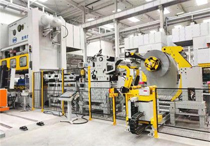
Coil Blanking Line
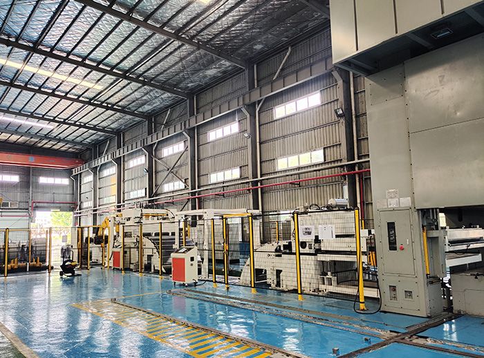
Applicable Material
Material Type: Uncoated cold rolled plate, Hot rolled pickling plate, High strength cold rolled plate, Galvanized plate, High strength hot rolled plate etc.
Material Thickness: 0.8-3.6mm
Coil Width: 200-1800mm
Yield strength: 245-980 N/mm2
Tensile Strength: 392-1180 N/mm2
Coil inner diameter: Φ610mm
Coil outer diameter: Φ1200-Φ1800mm
Loading weight: 20000KG
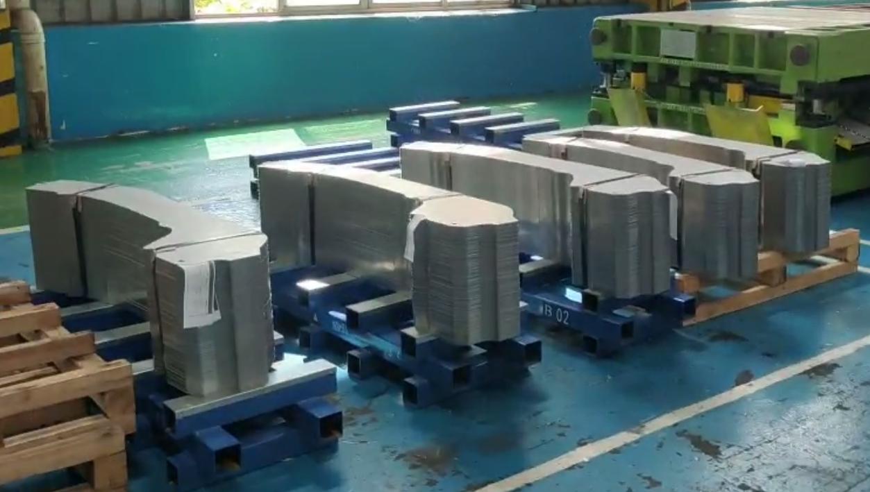
Finished Product
Finished Product Shape: Square, round or rectangular or irregular shape parts etc depends on the progressive die.
Finished Product Length: 40-2000mm
Finished Product Width: 200-1800mm
Length accuracy: ±0.15mm (≤500mm);
±0.3mm (>1000mm)
±1.0mm (Tail material)
Burr: ≤0.1*t(t=0.5~1.0mm); ≤0.05*t(t=1.1~3.0mm)
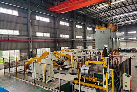
Line Speed of Coil Blanking Line
Leveling Speed: 0-60m/min
Feeding Speed: 0-60m/min
Press Machine Speed: 15-60SPM
Brief Profile of Coil Blanking Line
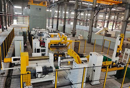
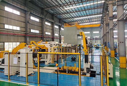
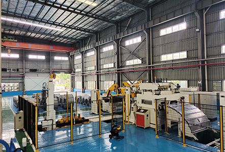
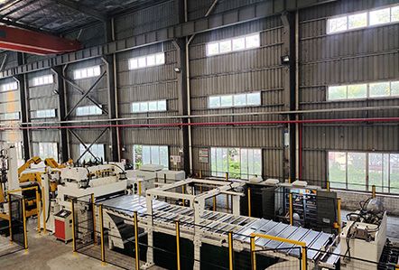
The coil blanking line is a new type of Automatic High Speed Coil blanking line which specially developed for stamping the thin, medium sheet plate with wide material and high yield strength of material.
The automatic coil loading and self-centering system is specially designed for fully automated operation. The leveling part of the equipment adopts the structure of six-fold rolling wheel and universal joint full shaft drive, which ensures the leveling accuracy better. The surface of the clamping roller is treated with hard chrome, which increases the friction between the roller and the coil strips to ensure the high feeding accuracy in the feeding process.
The innovative mechanical structure minimizes the working space required by the whole machine; Adopt Japanese servo motor to ensure high precision feeding; With the high-definition operation panel which is equipped with and safety protection system, even the green hands can also feel at ease to operate it; Sound operating system humanization design, will shorten the preparation work. Advanced automatic diagnosis system to assist the operator to quickly control the excellent performance of the machine; The design concept of enhanced safety factor makes the equipment have a longer safe service life; The control system has a large capacity of user product parameter information memory, as well as perfect equipment failure alarm system.
Main Parts of Coil Blanking Line
Coil Car
● This coil car has two functions. One helps coil load to the spindle of the decoiler machine, and other one is assisting the material head entering into the roller gap of straightening parts smoothly.
● When loading the metal coil with a narrow width, there are moveable baffles to avoid coil dump.
● The coil car has four guide columns load-bearing and the coil car contact surface is PU roller type.
● A hydraulic motor with chain transmission drives the two rollers.
● Loading weight: 20000kgs
● AC frequency conversion deceleration motor drives the coil car moving which will automatically decelerate when the coil moves close to the main shaft.
● A hydraulic cylinder drives the coil car lifting with pressure retaining valve for lifting smoothly.
● Coil Self-centering mode: Ultrasonic sensor automatically detects coil position and automatically self-centering (When coil outer diameter is less than 1600mm,manual press button operation is required for visual alignment).
● Offside preventing: Inductor proximity switch
● Moveable handle or touch screen panel control
Decoiler Machine
● After the coils holds on the spindle of decoiler machine, decoiler machine rotates intermittently to release the metal coil to metal strip, the support rollers on coil car will lead the strips into the straightener parts.
● Decoiler with support cantilever structure can loading up to 20ton. And there're three groups of hydraulic wedged structure for uncoiler spindle expansion. Moreover,
● Material auto-alignment function as an optional meet your requirements.
● Spindles driven motor: AC motor 45KW, with frequency converter
● Spindles transmission: Variable frequency reducer, double row, and large pitch chain drive
● Spindles brake: Cylinder disc brake
● Uncoiling Direction: From up to down
● Spindles support cantilever: Hydraulic Drive
● Coil Pressure arm: Add pressure on the coil to avoid strip lose during uncoiling process
● Coil Pressure arm material: Polyurethane rubber wheel
● Coil Pressure arm drive mode: Cylinder driving
Coil Guide Limit Arms
● Coil guide limit arms have two rollers.
● The inside rollers have a fixed angle, and the outer rolls can be open or close by air cylinder drive.
● When the two rollers are closed down, the metal coil will be fixed between two rollers, to prevent loop misguide.
● After coil uploaded on the uncoiler mandrel, the two rolls will be moved with self-centering to meet the setting coil width.
● The two rollers are non-motorized with free rotation, and the surface is black phosphorus treatment.
Straightener Machine
● The six-fold precision leveling structure is adopted to level the material and make its surface smooth, and the material is sent to the pressure equipment according to the set length and speed. The mechanism is mainly used to correct the material folding (length L direction) to make its surface smooth, for local tensile phenomenon on the surface of the material, may not be completely corrected. In addition, the width direction (C direction) of the coil cannot be corrected.
● Drive motor: 75KW, AC motor, with frequency converter (subject to actual design)
● Feeding roller: 2 pcs, the surface is made of ploughing sandblasting and electroplating hard chrome, HRC60±2
● Feeding roller lift drive: cylinder drive
● Feeding block: block range 200-1800mm, block vertical roller 4 (φ 65x90mm)
● Straightener rollers: 19 pcs, 9 top /10 on bottom (subject to actual design) (surface thickening) ,Electroplated hard chromium abrasive treatment, HRC60±2).
● Straightener Roller type: Six-fold t type
● Straightener Roller drive: each straightening roller is driven separately by a distribution gear through a cardan shaft
● Auxiliary roller: upper and lower two set, surface thickened hard chrome plating grinding treatment, HRC60±2.
● Straightener adjustment mode: According to the set value, the eccentric shaft is driven by the deceleration motor to adjust, and the encoder feedback signal controls the accuracy of the adjustment amount. The set value can be directly stored in the system database, and the next time you directly input the mold or product number, you can automatically adjust.
● Straightener value display mode: display by value on the touch screen, in addition, there is a dial indicator on the leveling body for reference.
● Feeding speed: 0-15m/min
● Straightening value set up: 0.1mm
● Straightener roller support: roller bearing
● Auxiliary roller support: roller bearing
The Bridge Device
● Function description: Guide flat smooth materials into the feeder platform, only touch screen manual operation, before automatic operation must be lowered to the bottom of the pit, to meet the safety conditions before operation.
● Bending radius: about 1600 mm
● Quantity of feeding platform: 1
● Depth detection: photoelectric sensing
● Looper pit length: about 4500 mm
● Looper pit depth: about 4500 mm
● Looper is mainly composed of arc guide roller, feeding table and optical induction detection. It is arranged between the continuously running straightening machine and the intermittent feeding device. Ultrasonic speed control ensures that there is sufficient sheet material in the looper pit to ensure intermittent feed to the blanking press or shears. The bending radius of R=1600mm ensures that no permanent plastic deformation of the material will occur when the material of different thickness and yield strength passes through the lopper.
● There are two arc-shaped guide rollers at the outlet and entrance of the looper. The rollers are made of polyurethane roller to prevent damage to the surface of the material. The roller chain adopts hinge structure. When the feeding table is lifted, the arc roller table can travel a flat roller table. The feeding table installed at the entrance and exit of the looper is driven by a hydraulic cylinder, and the roller table with material is passed between the looper to ensure the smooth passing of the material head through the looper;
● The feeding platform is equipped with three position detection sensors, which are the upper limit, the lower limit and the middle limit position.
● Upper limit: when in the horizontal position can allow the coil head go through;
● Lower limit: when the lowest vertical position, the material head goes through looper, feeding device, and the feeding roller closed, the feeding table automatically swing to the lower limit vertical position.
● Middle limit: When the tail material is processed, the position just ensures that the tail strip can not fall into the looper pit. When the feeding platform is lifted to the position, the feeding and straightening machine can run at the same time. Two photoelectric switches are arranged at the end of the two feeding platforms. When the material tail is processed, the feeding platform can automatically lift with the material and keep a certain distance to prevent the damage of the material. The looper height control adopts photoelectric induction detection to ensure the continuous and uniform operation of the straightening machine, to ensure the straightening quality, and to ensure that the feeding device can feed the blanking press at high speed and intermittently. At the end of one cycle, the straightener is reduced to slow speed until the very bottom of the looper pit is reached. When the strip is to be straightened, the feeding device will stop feeding.
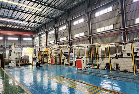
Limit Switch
● Function description: a set of width limit device is installed at the entrance of the feeder to eliminate the phenomenon of running sideways when the material with smaller width appears in the process of feeding.
● Structure description: there are a set of vertical guide rollers on both sides of the plate edge, and each set is fixed on a sliding seat. Each group is driven by the motor through the reducer and the screw pair to advance and retreat along the width of the plate, adjust and correct the plate of different widths. Equipped with proximity switch, automatically stop when guide plate contact sheet material.
● Width adjustment: hand wheel adjustment
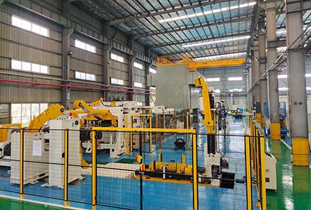
Prevent Back Device
● Function description: to prevent the reverse motion of the sheet when the servo feeder machine is opened, a sheet backoff stop device is installed in front of the servo feeder machine.
● Driving mode: open through the cylinder, in the case of pressure reduction or sudden power failure, the anti-retreating device can achieve quick clamping action by spring.
● Anti-retreat device: rubber plate form
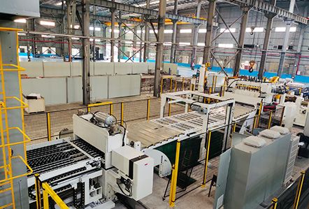
Fixed Length Servo Feeder
● Function description: Lead the coil strip to the press machine according to the set length and speed
● Drive mode: 30KW, AC servo motor (subject to actual design)
● Feeding roller: 2 pcs, the surface of ploughing sandblasting electroplating hard chrome, HRC60±2
● Feeding roller support: deep groove ball bearing
● Feeding Roller release mode: air pressure type
● Feeding Roller material: high carbon chromium bearing steel
● Feeding line height adjustment: Customized ±100mm
● Feeding Roller drive mode: gear box drive, all gear adopt nitriding and hard grinding 6 precision standard system.
● Feeding repeat accuracy: 0-1000mm ±0.15mm/m; 1000-2000 - mm + / - 0.3 mm/m
● Feeding line speed: 60m/min
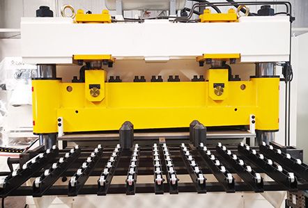
Hydraulic Shear
● Function description: hydraulic shear is mainly used for cutting a certain length of the head and tail that do not meet the requirements of use, and the cut waste will be collected and transported away from the production line.
● Maximum cutting width: 1800mm
● Cutting thickness: 0.8-2.5mm, in which the thickness in the range of 0.8-2.0 without adjusting the shear gap.
● Scissor action mode: hydraulic drive, touch screen click button operation, up and down with limit induction switch.
● Scissor gap adjustment: manual adjustment, using a feeler to determine the amount of adjustment.
● Direction of scissors action: the knife rest is downward to complete the cutting action.
● Scissors action times: 6spm/min
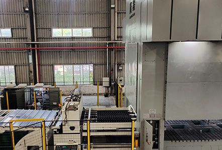
Micro Feeder Device
● Function Description: There is a telescopic tail feeding device at the end of the feeder outlet. When the tail reaches the main servo feeding device, the control system controls the roller closure of the micro feeder, the front end of the feeder roller is opened, and the tail feeding roller is sent into the mold production. The tail feeding device has the electric telescopic function. When extended, it can be close to the edge of the die to maximize the utilization of the coil strip, and when retracted, it can reach the outer edge of the working table plate.
● Wear-resistant Foley wheel is installed on the supporting frame to ensure the reliable transmission of the coil strip to the press and die after the sizing. The supporting frame of the micro feeder is arranged across to ensure the continuous support of the coil strip when it is telescopic.
● Expansion mode: motor driven, linear guide guide, screw drive.
● Expansion length: 0-1500mm from the left side of the table and 50mm outside the left side of the table (the actual size is designed according to the actual size of the punch press).
● Total length of bracket: 800-1500mm (designed according to the actual size of punch press)
● Micro transmitter sensor: photoelectric sensor
● Micro feeding accuracy: 0-1000mm ±0.15mm/m; ±0.30mm/m at 1000mm or above
● Micro feeding roller: 2 (upper 1 lower 1) surface for plough sand blasting electroplating hard chrome, HRC60±2
● Height adjustment: electric lifting
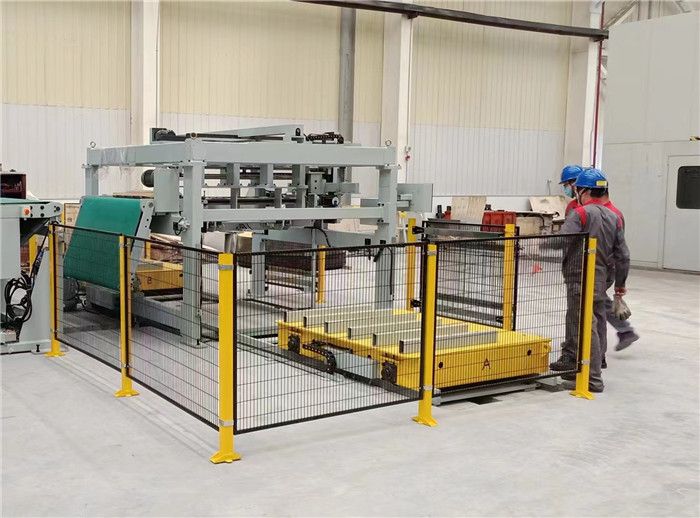
Automatic Stacking System
● The automatic stacking system is used to automaticaly stacking the cutting products,Combined with lifting platform and trolley, it can also transport neat stacking and chopping steel plates to the packaging area. The device is equipped with feeding device and automatic beating mechanism, which plays a good protective role on the surface of steel plates. In addition, the device has the length and width limit, automatic plate, automatic lifting and other functions.
● When it's automatic production, the stacking car moves to the receiving position, and the hydraulic lifting mechanism in the pit will lifting and ready to receive the cutting length sheets, and the same time the cutting length sheet is transferred to the receiving platform by conveyor belt, when the sheets fall down to the receiving platform from the conveyer belt and it will trigger the sensor to control the action of the flapping cylinder, and the action frequency of the flapping cylinder can be set in the system.
● At the same time of the sheet stacking, the car will gradually drop through the sensor console. When the sheet counting reaches the set value, it will output the signal to stop and wait for the next sheet receiving trolley to drop the material when it reaches the position, and the sheet starts a new round of sheet stacking.
Video of Coil Blanking Line


